David's Astronomy Pages
|
Notes (S357) |
Notes (Main) |
Home Page |
Notes (S359) |
|
Start up from Park. GPS fix achieved after 5 asterisks (developing range is 3 to 7).
Back to Top
Since the last session, I had updated my observatory profile to display graphs of focus profiles. Previously I had simply produced a table of data and calculated best focus result, and then plotted focus profiles during post-session analysis. Screen shots of the new graphing capability are shown below. They provide a easy to see / visual check on Focus position and Seeing Quality.
|
Collimination Sequence on +7th mag star (altitude 50 deg) |
|
|
| Measurement of peak FWHM before and after re-collimination |
Back to Top
PEC training was performed on the RA drive at the start of the session in order to try to reduce the effects of periodic error which were measured to be at least 20 arc secs during the first light session (S356).
Previous experience with PEC training with LX200 Classic had suggested that the hand controller would 'countdown' to the start of the training interval and then indicate when the training was complete some 8 minutes later (representing one cycle of the worm drive), however it turned out that training with the LX200R (GPS) was somewhat different ...
Training was initialised via the LX200 Autostar II handset
with auto-guiding performed using the main imager of the ST-10XME camera.
Instead of counting me down to the start of a cycle, the training
period began almost immediately with the current 'Segment'. After
progressing through 200 segments I thought that controller would indicate that
the training was over, but instead it just kept counting more segments.
After reaching 400 segments I decided to re-read the Manual section
"Periodic Error Correction", p.39. The paper copy of the manual
that I have reads "...Autostar
II display a count of the 200 positions of the worm drive, when the count
reaches 200, one cycle is complete. A full cycle takes around 8 minutes. Press
Mode to exit. With 20 minutes of training complete and confused why the
counter was now showing 500, I pressed the Mode button to exit from PEC
Training. To refine the training I followed it up with two
"Update" periods of around 8-9 minutes duration.
[ It is noted that in a downloaded electronic copy of the
LX200R manual the section on RA PEC training has been updated to read
"Autostar
II display a count of the 200 positions of the worm drive, when the count
reaches 600, one cycle is complete. A full cycle takes around 24 minutes. Press
Mode to exit.]
With PEC training 'complete' a series of 10 sec exposures was taken of a target object (M66) over a 17 minute interval. Analysis of these showed that whilst Periodic Error had reduced from previous level of 18-22 arc secs, the residual error was still significant - around 10 arc sec peak-to-peak. The error does not seem periodic (at least not on an obvious 8 minute cycle).
|
Performance with PEC On |
|
| Previous Performance without PEC |
|
In order to check the correction values compiled during PEC training the PEC table was downloaded from the mount, using the Meade PEC tool. The table was saved as a .csv file with 200 rows and imported into Excel for Plotting. The graph (below) has a general shape that mimics the general shape of the Periodic Error measured during 'First Light' session (S356).
|
Reading various newgroup postings suggested that the LX200R (GPS) actually has a
PEC table comprising 600 segments of 2.4 seconds each (equivalent to 3 x 8
minute cycles), rather than just 200 segments, but the Meade PEC tool hasn't
been updated to handle 600 segments.
The PEC table was therefore re-examined using an evaluation copy of the PEMPro
V2.6 by Sirius-Imaging. The PEMPro software was installed along with an
ASCOM driver for the LX200 GPS. Connection with LX200R scope was successfully established
and the PE Curve downloaded. This showed a 24 minutes of data (600
segments). with Peak to Peak PE of 33 arc secs.
|
Whilst data looks complete and periodicity is evident, there are some significant differences between cycles. It is suspected that PE curve is compromised by the premature ending to the 2-1/2 cycle training session and the short 'single cycle' Updates
|
It is clear that PEC training will need to be redone. It is hoped to perform this due an upcoming session, building upon the new knowledge and continuing evaluation of the PEMPro tool.
Back to Top
The larger field of view with 12" LX200R
+ ST-10XME and the greater sensitivity mean that new images are typically
containing many more stars, than my previous 8" LX200 + ST-7E setup. This
presents CCDSoft/TheSky with certain challenges, and means that Image Linking
(Plate Solution determination) is not only liable to fail, but means that
significant time is lost whilst the Bisque software and my own iterative Link
Finding routine attempt in vain to find a link.
Adjusting certain settings in CCDSoft source extraction setting, raises the
'star detection' threshold, reducing the detected stars and then allows
CCDSoft/TheSky to easily & quickly perform an Image Link.
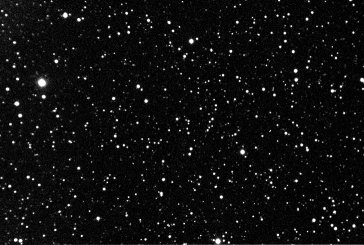
In the following example (star field around DY
Per, which indeed also presented link problems with with imaging equipment),
detection threshold settings of under 3.0 (under 8.0 for GSC stars alone) will
fail to link, and consume 5.7 secs looking for a match via CCDSoft, or 129
secs looking for a match using detailed iterative search link method.
Setting the Detection Threshold to 10.0 ensures
linking works for both USNO-B and GSC stars catalogs. This setting is used
during observatory imaging when the purpose is to rapidly perform image linking
for Locating Target Objects, or for T-Point Mapping.
The setting of 10 is not sensitive enough however to regularly ensure that
certain faint stars can be recognized during Photometric analysis. To pick
up DY Per at around mag +15, requires a Detection Threshold of between 3 and 5.
(if higher than 5-5.5 DY Per is not found, if lower than 3 then image linking
fails).
[Tests on another star RZ LMi at Mag +16.7, showed that certain 60s exposure
frames needed threshold to be set as low as 3.0 in order for the star to be
detected.
( 1 frame detected star at threshold of 10.0 / 1 frame detected at 5.0 / 1 frame
detected at 3.0 ) ]
| Image Link Trials | ||
|
Star Field with DY Per |
Inventory / Detection Threshold =1 GSC: No Link, USNO-B: No Link |
|
|
|
|
|
CCD Image (50% size reduction) 45s (single frame), 3x3 binning, V Filter 2009-03-21, (#358127), 12" LX200R (at f/5.7) + ST-10XME |
||
|
Inventory / Detection Threshold = 2 GSC: No Link, USNO-B: No Link |
Inventory / Detection Threshold = 3 GSC: No Link, USNO-B: Link / 178 stars |
|
|
|
|
|
Inventory / Detection Threshold = 5 GSC: No Link, USNO-B: Link 177 stars |
Inventory / Detection Threshold = 10 GSC: Link / 165 stars, USNO-B: Link / 165 stars |
|
|
|
|
Back to Top
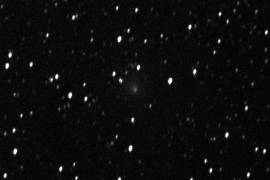
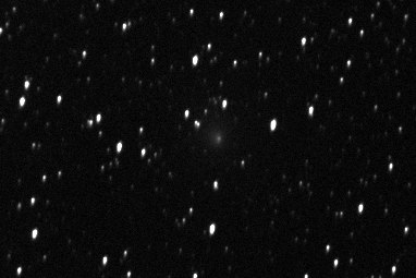
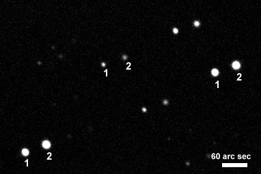
Problems were noticed with a batch of images of C/2009 T2 (Cardinal)
where each frame shows a distinct and consistently orientated star elongation.
Analysis indicated that the elongation wasn't due to a N-S drift.
|
Two frames of C/2009 T2 (Cardinal) showing Star Elongation Sky Position 307 deg Azimuth, 34.4 deg Altitude |
|
|
|
CCD Images (cropped to central area) 30 sec exposure (single frame), 3x3 binning, C Filter 2009-03-21 23:21/ 23:23 h UT (#358136 & 39) 12" LX200R (at f/5.7) + ST-10XME |
Back to Top
Drift Align Checks were made to determine the accuracy of the telescope's Polar Alignment. The N-S drift of a star in the Southern Sky (near to Meridian & Declination 0) and the N-S drift of a star close to the western horizon (West Sky Point) were measured from images taken 12 minutes apart.
The N-S drift rates reveal that the Polar Axis of the
telescope mount is
a ) pointing 1.04 arc mins too far west (requiring that wedge is rotated
very slightly clockwise)
a ) pointing 5.39 arc mins too low (requiring that polar axis is slightly
raised)
Images pairs - Binning 2x2, Plate Scale 1.612, Exposure 10 secs.
| Log file associated with Polar Alignment Check |
|
Slew to South
Sky Point Measuring N-S
Drift |
|
- South sky point (Northern
Hemisphere)
|
|
Slew to West Sky Point Measuring N-S
Drift Taking 10s image (C)...
Ok [00358004] 19:59:49UT
Full 2x2 10s C |
|
- West sky point (Northern
Hemisphere) |
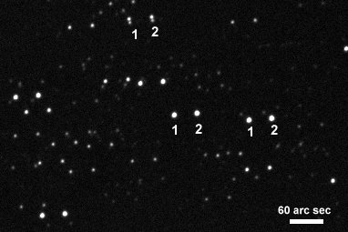
The image pairs also confirm previous indications that stars are drifting westwards in RA, showing that the scope is tracking slower than sidereal time - see below
|
Drift Align Images - South Sky Point Frames taken 12.65 minutes apart Dec drift 0.27 arc sec/min northwards RA drift 3.2 arc sec/min westwards |
|
|
CCD Images (stacked & cropped to central area) 2 x 10s sec exposure (sum combine), 2x2 binning, C Filter 2009-03-21 (#358002-03) 12" LX200R (at f/5.7) + ST-10XME |
|
Drift Align Images - West Sky Point Frames taken 12.07 minutes apart Dec drift 1.38 arc sec/min northwards RA drift 4.1 arc sec/min westwards |
|
|
CCD Images (stacked & cropped to central area) 2 x 10s sec exposure (sum combine), 2x2 binning, C Filter 2009-03-21 (#358004-05) 12" LX200R (at f/5.7) + ST-10XME |
Back to Top
Previous two sessions (S356 & 357) had indicated that the
scope is drifting in RA during tracking by around 1.9 arc sec/minute (after
removing effects of Periodic Error).
Image pairs used for Polar Alignment Check (see images above) were further examined for
RA drift. They show that stars are drifting westwards
in RA by between 3.2 and 4.1 arc sec /minute. This is much more than
can be explained by the relatively small polar mis-alignment. The combined datasets suggest that the
scope is tracking slower than sidereal
time by around 0.3%
Analysis
| South Sky Point | Stars drift westwards by 25 pixels in 12.65 minutes, equivalent to a rate of 3.2 arc secs/minute |
|
| West Sky Point | Stars drift westwards by
31 pixels in 12.07 minutes, equivalent to a rate of 4.1 arc secs/minute. |
Since sidereal motion is 15 arc min/min (or 900
arc sec/min), the tracking is therefore running slow by around 0.34%
[ 3.2 arc sec/min = 0.344% slow, 4.1 arc sec/min = 0.47% slow,
1.9 arc sec/min = 0.21% slow ]
[ The slightly higher values in this session might be caused by an incomplete and
therefore 'biased' PEC table. ]
Back to Top
A few days later (2009-03-26) a trial run was made in which
the LX200R tracking rate was adjusted to a custom setting of
"+3" using the AutoStar II controller. (Setup/Telescope/Tracking Rate
Adjustment). This setting should equate with a rate "Sidereal Rate +
0.3%" and thus should negate the estimated 0.3% slowness in the scope's
normal tracking..
A series of 20 sec images were collected at 3x3 over a 50 minute period of a
star field positioned approximately Due South / Declination 0 deg. The
conditions were to windy to collect useful observations or even half-decent
images, but they were sufficient for the task in hand despite frequent wind
shake. Despite the poor quality it was an encouragingly fact that nearly
although the images still managed to successfully achieve a plate solution (via
TheSky).
The amount of star drift is shown in the left hand figure
below. Whilst the "+3" guiding rate adjustment did remove the
previous westerly star drift, it was replaced instead by a roughly equal
amount of easterly star drift (with a rate of 2.5 arc mins /
minute).
The next session will examine performance with "+1" and "+2"
guiding rates in order to find the best tracking rate.
[one newsgroup posting that I've seen suggests that tracking rate is
partially temperature dependant ].
|
After subtracting the average star drift (right-hand figure above) a residual error of 20 arc secs remains. A cycle on the order of 24 minutes is noticeable that is most probably associated with an incompletely trained PEC table. (see Pec Training above). After a gap of several minutes data around the 50-51 minute point, shows less extreme easterly drift. This excursion is more extreme that can be explained by the 20 arc min error range associated with first 40 minutes of data.
Notes : A subsequent Power Down/Power Up cycle showed that the Custom Tracking Rate entered (+3) is not retained, but instead Tracking Rate is reset to 'Sidereal' (but with the rate that has previously been shown to be slow). [Ideally Tracking Rate would be a setting that is retained during Power Down/Up cycles.]
Back to Top
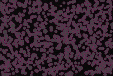
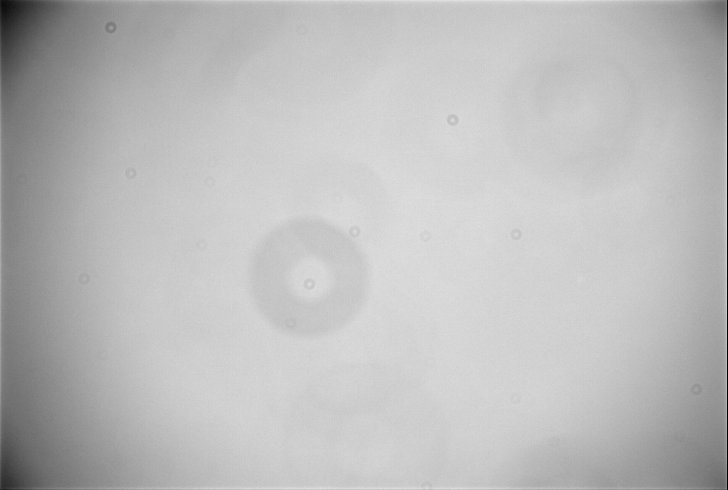
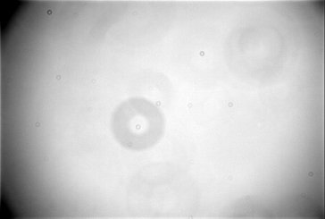
A few days later (2009-03-26/27) opportunity was taken to acquire sets of Flat Frames, at 1x1, 2x2 and 3x3 binning using Dawn Sky with Semi-Dithering. These were the first high S/N flat frames taken through the scope, previous flats were taken using Moon-Lit Night Sky.
Flats were taken through through a Clear (C) filter, with
master flats created using "Sigma Beta 10" after normalizing flat
frames for the developing sky brightness.
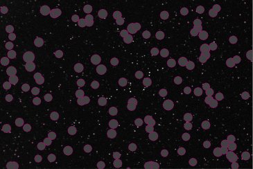
Typical range of Flat Field features are evident.
- Vignetting (dark corners)
- Small 'dust' motes due to particles on the CCD cover
- Larger 'dust'motes due to particles on the Camera/Filter Wheel
Window
- Larger still but fainter dust motes due to particles/dirt on Filters
themselves.
| Example Master Flat (3x3 binning) - Session 358b |
|
|
Master Flat Frame 18 x 0.5s exposure (verage combine), 3x3 binning, C Filter 2009-03-26, 12" LX200R (at f/5.7) + ST-10XME |
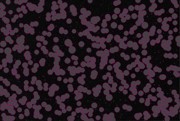
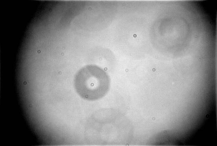
| Flat Frame - detail |
|
|
Master Flat Frame - alternate Black/White range Image details as above |
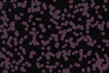
| Flat Analysis Map (CCD Inspector) |
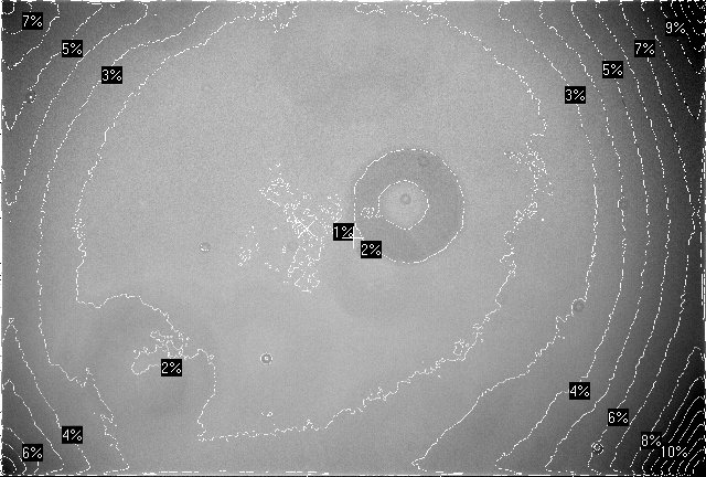
|
|
Master Flat Frame 15 x 1s exposure (average median combine), 1x1 binning, C Filter 2009-03-26, 12" LX200R (at f/5.7) + ST-10XME |
In addition a slightly brighter patch of pixels is noted in several Filter Flats (just below center line on right hand side of above image). The patch is not thought to be related to a star as frames were differed and then combined by Median Average.
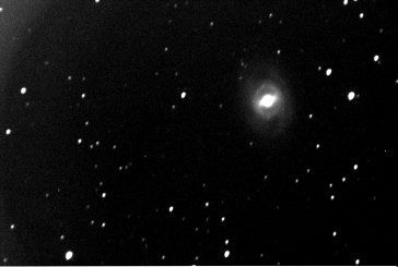
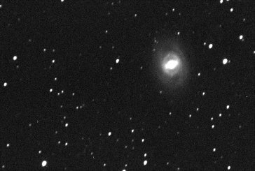
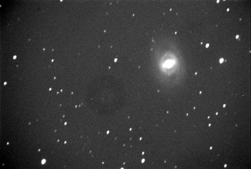
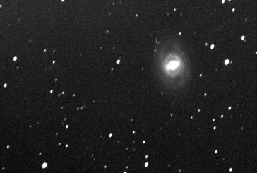
| Impact of using better Flat Frame | ||
| M95 with previous Moon-Lit Sky Master Flat | M95 with new Dawn Sky Master Flat | |
|
|
|
|
CCD Image (50% size reduction) 120s (single frame), 3x3 binning, C Filter 2009-03-22, 12" LX200R (at f/5.7) + ST-10XME |
CCD Image (50% size reduction) Image details as left |
|
Back to Top
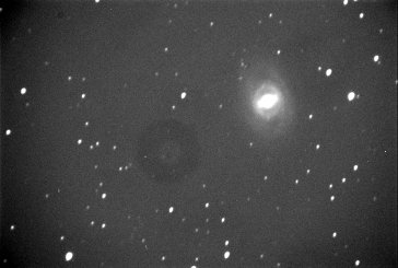
| M95 - Flat Framing Trials | ||
|
M95 (dark subtracted / no flat frame) notice vignetting and large dust mote |
||
|
||
|
CCD Image (50% size reduction) 120s (single frame), 3x3 binning, C Filter 2009-03-22, 12" LX200R (at f/5.7) + ST-10XME |
||
|
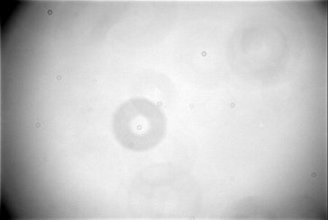
M95 - reduced with 'Compromised' 'Master' flat
frame (Dawn Flats) vignetting and large dust mote fainter but still obvious |
Compromised 'Master' flat frame' (Dawn Flats) low noise, should be good for flat fielding ! ' double normalised ?' (Mode Value : 43500 ADU) |
|
|
|
|
|
CCD Image (50% size reduction) Image details as above |
Flat Frame (50% size reduction) 19 x 0.5s exposure (normalised & median average combined) 3x3 binning, C Filter 2009-03-26, 12" LX200R (at f/5.7) + ST-10XME |
|
|
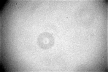
M95 - reduced with Single flat frame (Dawn Flat) vignetting and dust mode removed but a top to bottom gradient is present |
'Single flat frame' (Dawn Flat) more noisy flat, should work as well as Master ? (Mode Value : 36500 ADU) |
|

|
|
|
|
CCD Image (50% size reduction) Image details as above |
Flat Frame (50% size reduction) 0.5s exposure (single frame), 3x3 binning, C Filter 2009-03-26, 12" LX200R (at f/5.7) + ST-10XME |
|
|
M95 - reduced with 'New Master Flat' (Dawn Flat) vignetting and dust mode removed but a top to bottom gradient is present (more obvious than with single frame ?) |
New 'Master' flat frame' (Dawn Flats) Average 18 frames (Highest ADU frame dropped) (Mode Value : 33500 ADU) |
|
|
|
|
|
CCD Image (50% size reduction) Image details as above |
Flat Frame (50% size reduction) 18 x 0.5s exposure (normalised & average combined) 3x3 binning, C Filter 2009-03-26, 12" LX200R (at f/5.7) + ST-10XME |
|
|
M95 - reduced with 'New Master Flat' (Dawn Flat) and Gradient Corrected |
||
|
|
||
|
CCD Image (50% size reduction) Image details as above |
||
Back to Top
In addition to flat filter sets for making Master Flats (C
filter), small sets of 3 flat frames (2x2 binning) where taken through
each filter to examine differences between different Filter Flats.
These are shown in the montage below,.
These showed that B,V,R Filters flats were relatively similar to the the Clear
Filter Flats, though there were differences associated with the diffuse/fainter
motes associated with particles and dirt on individual the filters
themselves. However some filters showed additional differences.
The Red Filter show a brightened area that is repeatable.
However the bright feature is not seen on the R Flat filter, suggesting a slight
defect/issue with the Red filter, rather than a wavelength dependant feature.
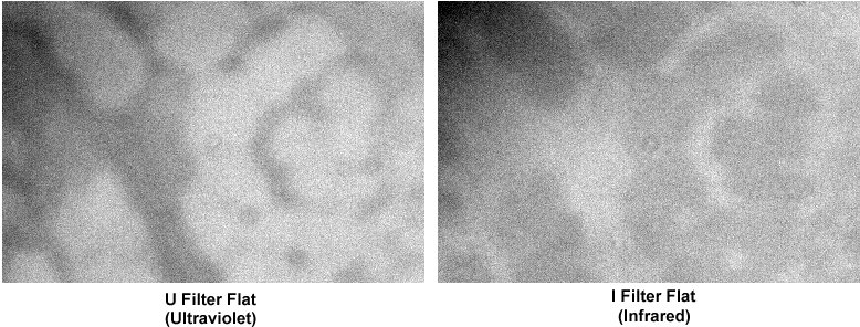
More noticeable was a blotched patterns on U Filter Flats. At first it was
thought this was due to a very dirty or otherwise defective U filter. However it
was noticed that I (infrared) Filter Flats also showed similar shaped blotches,
but they were fainter and 'opposite' in magnitude (ie dark areas on U filter
flats where lighter on I filter flats and vice versa). This suggests that
there is some material 'grease?' on the surface of the CCD or Camera Window,
that absorbs light in one wavelength band (U or I ) and re-transmits it in
the other wavelength band.
|
|
Montage of Flat Frames by Filter 3 frame stacks (average combine), 2x2 binning 2009-03-26, 12" LX200R (at f/5.7) + ST-10XME |
The blotching see on the U and I filter whilst fainter is still just recognisable on the B and Blue Filter Flats. Since the material is probably difficult to see (though UV light source might show it), it might be difficult to know what surface to clean or whether cleaning was effective and therefore I will hold off from trying to perform any remedial treatment.
Since the U filter will be used for imaging bright targets such the Moon and Venus, without saturating the ST-10XME camera at the minimum exposure of 0.12 sec, it will be obviously be important to use U Filter Flats. My existing Moon filter is not sufficiently light blocking to bring the exposure levels within the > 0.12sec range. Whilst stopping down the front of the telescope would work, this operation is obviously inconvenient for remote/automated operation of the scope for imaging multiple targets.
| U and I Filter Flats - Detail Compared |
|
|
Montage of Cropped Flat Frames taken through U and I
filters 3 frame stacks (average combine), 2x2 binning U filter : 3 x 3 sec exposure / I filter : 3 x 0.2 sec exposure 2009-03-26, 12" LX200R (at f/5.7) + ST-10XME |
Back to Top
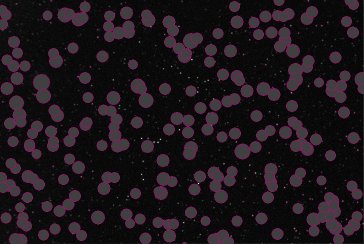
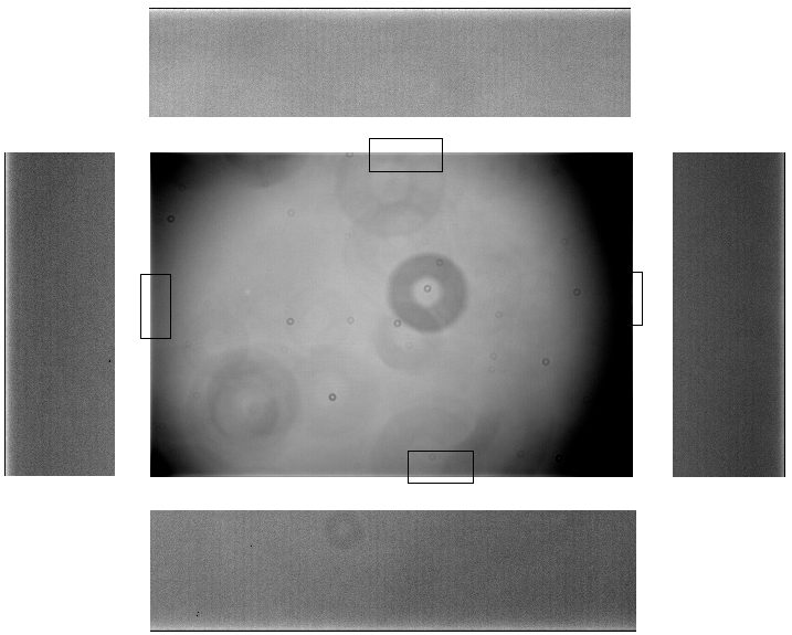
Images taken with ST-10XME suffer from some minor edge effects, which may produce anomalies lines along the top, bottom and sides of certain images. These lines are noticeable on flat frames as shown below. The brightening is presumed to be due to light reflecting off slightly raised edges to the CCD chip.
| CCD Image Effects |
|
|
Master Flat Frame 15 x1 s sec exposure (median average combine), 1x1 binning, C Filter 2009-03-26, 12" LX200R (at f/5.7) + ST-10XME |
Back to Top
| This Web Page: | Notes - Session 358 (2009-03-21) |
| Last Updated : | 2015-05-16 |
| Site Owner : | David Richards |
| Home Page : | David's Astronomy Web Site |