David's Astronomy Pages
Observatory
Design, Construction & Modifications
Observatory
Home
Page
Telescope
David's Astronomy Pages
|
Observatory |
Home Page |
Telescope |
This page describes the design, construction and later modification to my roll-off roof shed observatory.
I had owned an 8" LX200 telescope for 3 years up to 1998, and had used it for viewing various planetary, stellar and deep-sky objects from a patio in the garden. The task of setting up the tripod and telescope, aligning it each session had became a somewhat unwelcome chore, and I was finding that I was using the telescope less and less.
In order to make my visual observing more frequent/more pleasurable and in anticipation of the day when I might get an ST-7 CCD imager which would benefit from a permanent setup, I built myself a roll-off roof observatory in my rear garden in which to permanently mount my LX200. Details of the design and construction of the observatory and the permanent pier are given below.
Because of the high likelihood that I will need to move with my job in the future, the observatory and pier were designed that they can be removed and taken to a new site should the need arise. This feature of the design was tested during the course of 2000/2001 when I moved to southern England. The observatory was successfully dismantled and then, after some time in storage, reassembled at a new site in Dorset (see Kingcup Observatory). The observatory was again dismantled and moved in 2003/2004 to a new site back in Scotland (see Clair Observatory)
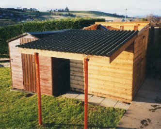
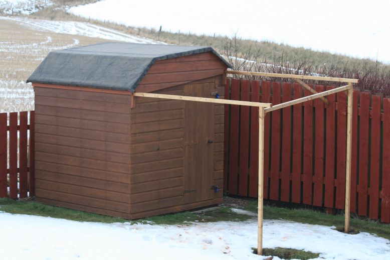
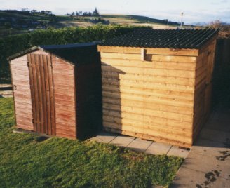
The two photos below show the observatory in its original and current forms.
| Observatory (1996) | Observatory (2009) | |
 |
 |
Back to Top
For anybody thinking about building an observatory themselves I thoroughly recommend looking round on the internet to get an overview of the various designs, experiences and lessons of others. For me it provided ideas, inspiration and confidence to embark on the project and complete it within about 6-7 weeks.
Useful sites/documents that I found back in 1998 were
A source of information that I've since found out is the
ATM Observatory
Plans Page
(Note : the above external links, if they still exist, will
open in a separate window)
Besides reading web articles I also contacted a number of amateur astronomers by e-mail and asked for their experiences and suggestions - I was surprised by the quick response, less than 36 hours in each case. Thanks guys.
Back to Top
The first task was to select the best location for the Observatory. I was
limited to using my back garden which lies in a village in NE Scotland. After
a little consideration the best spot appeared to be on the site of our existing
garden shed, which offered the most reasonable view of the sky (south, west
and north), was fairly close to the house and was shielded from direct light
pollution, (provided I shifted the existing garden shed over by 2 metres into
a position blocking the worst offending street lamp light).
The village suffers a moderate, but not overwhelming amount of light pollution.
Light Pollution is worst when clouds are about, but I normally observe when
skies are completely clear.
Back to Top
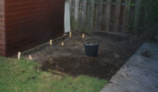
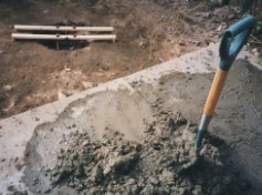
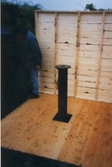
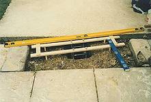
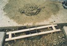
An existing shed stood on the site and was first moved to an adjacent position. The site was then levelled down to a new deeper level, using spade, wooden posts and spirit level.
 |
|
Preparing the site |
Back to Top
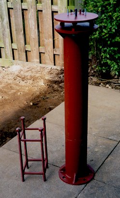
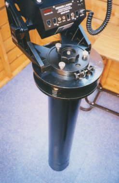
A locally based Engineering Firm (Sun Engineering, Aberdeen) made up the Pier from the designs I provided. The pier was 7" OD in diameter and 3' 8" tall. The top and bottom plates were 1/2" in thickness and had holes drilled to later bolt the pier to the ground and to bolt on the Pier to Wedge Mount. A 3" ID hole was drilled in the upper plate that would allow sand to be late poured into the pier tube for vibration dampening purposes. The plates were welded to the tube and then four 2" tall triangular fins were welded between the pier tube and the bottom plate for additional stability, whilst three 2" tall triangular fins were welded between the pier tube and the top plate.
 |
| Engineering Drawing (larger view) |
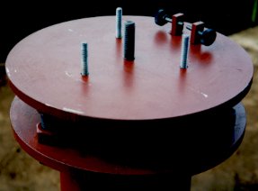
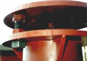
A further 1/2" thick circular plate was made for the Pier to Wedge Mount. 3 bolts were welded to the lower surface that would allow fitting to the top plate of the pier and levelling of the Pier to Wedge Mount. A central bolt and 3 surrounding bolts were fitted to the upper surface that would later accept the Meade Equatorial Wedge. A device was also installed to the upper surface that would allow screw directed force to be exerted on the lug on the wedge that would rotate it left or right for alignment purposes. Initially coated in Red Oxide paint, the Pier was painted Black prior to its installation.
|
| Engineering Drawing (larger view) |
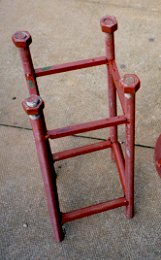
The Engineering firm also made a bolt-cage that would be set in a concrete base to take the pier.
The total cost of the Pier, Pier to Wedge Mount and bolt-cage was £280 (1998)
| Pictures of the Pier | |
|---|---|
 |
|
Back to Top
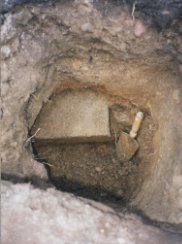
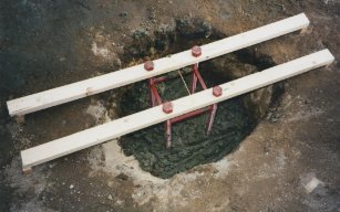
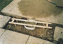
Once the site was cleared and leveled, the location for the hole for the pier base was marked out. The hole was dug out in the shape somewhat like an chemistry flask, with a wide flat base and a narrower neck. The hole was 30" deep, 30" diameter at the bottom and 20" diameter at the top. Whilst the upper section was known to be made-ground an unexpected surprise was finding a complete concrete breeze block, which had to be removed. The base of the hole was a damp clay subsoil formed from the underlying boulder clay deposits we have here.
Once dug the bolt-cage for the pier was hung in the hole from a temporary cradle made out from two lengths of 1.1/2" x 1/2" batten supported on surveyed and levelled marking posts. The position of the bolt cage was carefully checked and adjusted by 1) checking that the centre of bolt-cage was at the surveyed center position of the observatory site, 2) checking that the compass bearing of the bolt-cage cradle against the compass bearing of a orientation of a set of known pier align points defined on a previous evening. 3) cross-checking that bolt-cage cradle was parallel to those same known pier align points 4) checking that the bolt-cage cradle was vertical
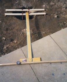
The pier align points were defined by setting up the pier, wedge and telescope at nighttime on the flat paved area adjacent to the observatory site and then performing a polar alignment by carefully rotating the pier (note the Wedge was positioned in the centre of its range of Pier to Wedge adjustment at this stage). With this done the positions of the screw holes on the base of the Pier was marked on the underling paving stones.
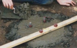
The hole was then filled with concrete ballast (a total of around 375 kg), which was mixed directly adjacent to the site. Checks were made on the position and orientation of the bolt-cage through the operation. After letting it stand for a while the Cradle support was temporarily removed and a circular dam placed around the top of the bolt-cage,which was then filled with more concrete and smoothed off as best as possible. The cradle battens were then replaced and the concrete left to set overnight.
Whilst the attempt to smooth off the top of the concrete was ok at a first pass, it was clear that it wound not provide a flat stable base for the pier and consequently the top of the concrete was finished off with a layer of floor levelling compound. Once not of great strength (too much humidity & water around ?), it did produce the required level base.
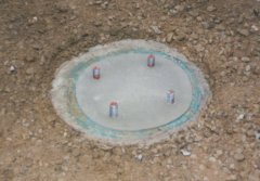
The site was then finished over with gravel and sand up to the level of the tops of previous levelled wooden survey posts. A small amount of work was required to strengthen the downdip end of the site, between it and the newly repositioned older shed. Concrete garden slabs were then laid on the sand/gravel base.
Total cost for the Pier Base and Flagstones was £53 (1998)
Back to Top
I initially started with idea of having a building structure of 7' by 7'. But I eventually pruned this back to 6' 6" x 6' 6" after setting up my LX200 in our living room and surrounding it with chairs to define the minimum comfortable space needed. I decided that a custom-made pent (sloping) roof garden shed with a door, but no windows would be the best design. Having chosen a height of 3' 4" as the height needed between Floor and Base of Wedge I decided upon a shed height of 5'6" at the front (which would face south) and 6'2" at the rear (which would face north). The floor of 3/4" plywood was specified to have a 12" square hole cut exactly in the centre, allowing it to fit over the Pier (largest diameter 11"). Fixed to 2.1/2" x 3" battens and resting on three 6" x 2" wooden battens, the floor of the shed rests 5" off the ground. In order to make roof as light as possible for rolling off I decided that I would make roof from corrugated bitumen sheets (Caroline) rather than take a standard wooden roof + felt and agreed with the Shed maker (G.C. Carle & Son, Parkhill, Dyce, Aberdeen) that he would provide the Roof Framework only. Total cost including basic lock, delivery and erection was £407 (1998)
The shed frame was made with rough sawn wood, and a day was spent sanding down the inside of shed and giving it a coat of Timber-Care. Experience during the first 2 weeks showed that some water was entering the shed along the base of one wall, during conditions of rain combined with strong wind. The shed maker gave me 4 extra boards, which I retrofitted around the bottom of each wall and seems to have cured the problem.
An additional problem that required some attention was the plywood floor which was initially weak along the join between the two sections from which it was constructed. Retrofitting a length of 4"x2" wood beneath the flooring along the line of the join strengthened the floor considerably.
The floor of the shed has been covered by a vinyl floor covering, the hole in the floor around the pier has been filled by a removable 2 part cover and additional locks / security have been added.
The shed does not as yet have its own electrical power outlet, but this is an option for the future.
Back to Top
In order to make roof as light as possible for rolling off I decided that I would make roof from corrugated bitumen sheets (Caroline) rather than take a standard wooden roof + felt and agreed with the Shed maker that he would provide the Roof Framework only.
(As it turned out the roof is pretty heavy in any case - corrugated bitumen turns out to be pretty heavy - and requires 2 people to lift it into position, however roll-off operation is pretty easy and can easily be managed by one person).
Corrugated Bitumen sheets were trimmed where necessary and nailed to the roof framework using the Caroline system of nails & plastic bungs. The wooden surrounds were then fitted around. and Caroline system white poly-foam fitted in the eves.
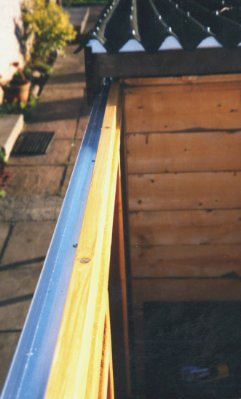
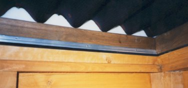
Meanwhile lengths of right-angled aluminum were cut and screwed to the top of the left and right hand walls of the shed, and wooden stops fitted to top of the front and rear walls of the shed. The former of course needed to be narrower than the width of the roof in order to allow wheels of the roof to 'pass through the front face of the shed.
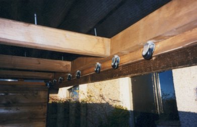
Castor wheels where fitted to the base of the roof, by drilling tight fitting holes and firmly gluing the castor 'pins' into position. It was original thought that 4 wheels on each side would be sufficient, but it was soon realised that more would be needed and in the end 8 wheels were fitted on each side. Wooden stops were fitted to the back of the roof so that it wouldn't easily roll all the way off and locking devices were fitted to the outside front face of the shed and the inside rear wall of the shed.
|
|
After a few teething problems which required final adjustments the roof now
operates pretty well. I worry that it will get stuck when I'm tying to roll-it
back after a late night of observing, but it hasn't happened yet ("fingers
crossed")
[Note : After a couple of shed relocations, the design started
to failed in 2004-2005 whereby some of the wheels would loosen and twist causing
the roof to jam when shutting. Remedial fix was employed involving moving the
wheels from the sides of roof to new positions on the tops of the observatory
sidewalls [ see Roof Changes
(June 2005) ].
Seals and additional wooden battens were on the inside side of the left and right hand walls of the shed were successfully used to make the Observatory pretty weather tight.
After fitting the roll-off locking devices, but before I got round to fitting proper locking devices for the roof disaster stuck ! The tail end of the Hurricane Mitch (which had produced so much devastation in Central America) then came across to Scotland and produced strong violent gales in our area on the afternoon of 1998-Nov-09. The weight of the roof was insufficient to stop the wind from sucking up and lifting the front edge of the roof. The full force of the wind then got under the roof and flipped it over over the garden fence into a neighbors garden. It was luckily still in tact when retrieved and the damage was repairable. Since then latches have been fitted inside the shed which secure the roof down, yet are simple to unlatch and latch again when needing to operate the roof.
|
|
Opening & Closing the Observatory (Click on following links in Sequence)
3) Push back the
roll-off roof |
Back to Top
With all the careful design and construction completed successfully, installing the telescope was a fairly simple matter of screwing on the wedge to the pier, lifting on and screwing down the LX200 and then waiting for the next clear night to perform polar alignment.
 |
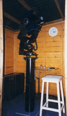 |
First light with the telescope in its new observatory housing was on 1998-Oct-23.
Back to Top
Total cost for the Observatory came to £ 910 (1998). This was pretty close to my budget estimate of £ 900. A breakdown of the costs is as follows :
Shed (6'6" x 6'6") £ 407 Roll-Off Roof £ 96 Pier £ 280 Concrete Pad £ 23 Flagstones (base of shed) £ 30 Additional Lock/Security £ 23 Vinyl Floor Cover £ 26 Other £ 15
Back to Top
Back to Top
The observatory and pier were designed so that can be removed and taken to a new site when the need arose. This feature of the design was fully tested during the course of 2000/2001 when I moved to southern England and set up the observatory at the Kingcup site.
A new bolt cage was made my a local engineering couple (I got them to make to two !)
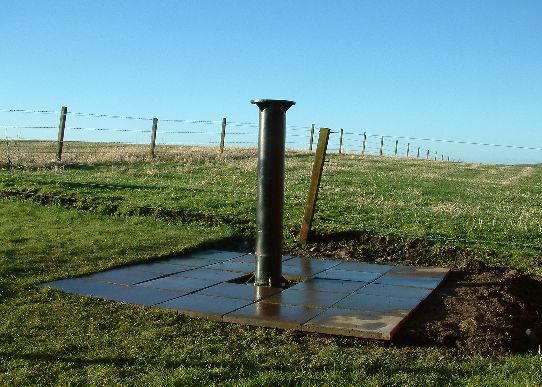
Photos showing preparation of the new pier base for the observatory at the
Kingcup site are shown below:
|
|
|

|
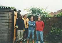
With the pier base constructed and the pier in place I had some work colleagues help me to erect the shed observatory
|
The construction plan that was used for re-erecting the observatory at the Kingcup site is listed below.
| Task | Description |
| 1 | Shed Location |
|
1.1 |
Decide optimal location for telescope (?observing trials) |
|
1.2 |
Decide optimal orientation for shed / sliding roof supports |
|
1.3 |
Decide cable routing options / decide voltage |
| 2 | Bolt Cage |
|
2.1 |
Measure pier base holes for bolt cage dimensions. (Record for Future) |
|
2.2 |
Select Engineering Firm. Place Bolt Cage Order |
|
2.3 |
Collect Bolt Cage |
|
2.4 |
Construct second bolt case holding batten |
| 3 | Site Preparation |
|
3.1 |
Clear Site |
|
3.2 |
Level Site / Insert Levelling Posts |
| 4 | Site Survey |
|
4.1 |
Emplace Level Slab |
|
4.2 |
Position Pier/Wedge/LX2000, align with Pole Star, Mark Base Holes |
|
4.3 |
Align Holding Battens, Insert Alignment Posts |
| 5 | Pier Installation |
|
5.1 |
Acquire Cement & Ballast |
|
5.2 |
Dig Hole |
|
5.3 |
Mix Concrete / Emplace Bolt Cage |
|
5.4 |
Emplace Bolt Cage in Cement |
|
5.5 |
Leave to set / Cover |
|
5.6 |
Level Top / cover |
|
5.7 |
Bolt down Pier |
| 6 | Sheb Base |
|
6.1 |
Lay Sand& Ballast Base, Level Off |
|
6.2 |
Lay Slabs |
| 7 | Shed Erection |
|
7.1 |
Enroll helpers |
|
7.2 |
Strengthen/repair roof |
|
7.3 |
Paint Roof |
|
7.4 |
Erect Shed / Put On Roof |
|
7.5 |
Adjust Roof / Fittings |
|
7.6 |
Survey Roof Support Positions |
|
7.7 |
Construct Roof Support Boxes |
|
7.8 |
Install Roof Support Boxes |
| 8 | Shed Fitting |
|
8.1 |
Put Down Flooring |
| 9 | Telescope Fitting |
|
9.1 |
Cut Rubber Pad |
|
9.2 |
Fix Wedge / LX200 |
|
9.3 |
Align Wedge/ Telescope |
| 10 | Cabling |
|
10.1 |
Fit conduit through House Wall |
|
10.2 |
Run Cabling between House and Shed Observatory |
|
10.3 |
Tie In Cabling in Shed |
|
10.4 |
Tie In Cabling in House |
|
10.5 |
Test Cabling |
Back to Top
The observatory and pier were relocated again in 2003/2004 when I returned to Scotland, but to a new location north of Aberdeen (Clair Observatory).
I already had a spare bolt cage left from the relocation three years earlier which I then used in the preparation of a new pier base at the Clair site.
 Pier & observatory base (larger) |
With the assistance of a couple of friends I erected the shed observatory in its new location:
 Clair Observatory (roof open) |
As with Kingcup site, the observatory was supplied with electricity, but this time wireless connectivity was used for remote operation, instead of Ethernet cabling.
The full construction plan that was used for re-erecting the shed observatory
at the Clair site is shown below:
| Task | Description | |
| 1 | Shed Location | |
|
1.1 |
Decide optimal location for telescope (?observing trials) |
|
|
1.2 |
Decide optimal orientation for shed / sliding roof supports |
|
|
1.3 |
Decide cable routing options / decide voltage |
|
| 2 | Bolt Cage | |
|
2.1 |
Recover bolt cage / bolt cage holding batten from storage. (two bolt cages were made at time of Kingcup Observatory) |
|
| 3 | Site Preparation | |
|
3.1 |
Clear Site |
|
|
3.2 |
Level Site / Insert Levelling Posts |
|
| 4 | Site Survey | |
|
4.1 |
Emplace Level Slab |
|
|
4.2 |
Position Pier/Wedge/LX2000, align with Pole Star, Mark Base Holes |
|
|
4.3 |
Align Holding Battens, Insert Alignment Posts |
|
| 5 | Pier Installation | |
|
5.1 |
Acquire Cement & Ballast |
|
|
5.2 |
Dig Hole |
|
|
5.3 |
Mix Concrete / Emplace Bolt Cage |
|
|
5.4 |
Emplace Bolt Cage in Cement |
|
|
5.5 |
Leave to set / Cover |
|
|
5.6 |
Level Top / cover |
|
|
5.7 |
Bolt down Pier |
|
| 6 | Shed Base | |
|
6.1 |
Lay Sand& Ballast Base, Level Off |
|
|
6.2 |
Lay Slabs |
|
| 7 | Shed Erection | |
|
7.1 |
Enroll helpers |
|
|
7.2 |
Erect Shed / Put On Roof |
|
|
7.3 |
Adjust Roof / Fittings |
|
|
7.4 |
Re-Lay Flooring |
|
|
8 |
Cabling | |
|
8.1 |
Fit conduit through Garage Wall |
|
|
8.2 |
Run Power Cabling between Garage and Observatory |
|
|
8.3 |
Tie In Cabling in Shed / Tie In Cabling in Garage |
|
|
8.4 |
Test Cabling |
|
| 9 | Telescope Fitting | |
|
9.1 |
Cut Rubber Pad |
|
|
9.2 |
Fix Wedge / LX200 |
|
|
9.3 |
Align Wedge/ Telescope |
Back to Top
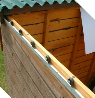
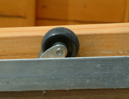
The roll-off roof was originally constructed with sets of wheels along each side of the roof. These ran along rails mounted on the top of each sidewall of the observatory and allowed the roof to be rolled-off/on. Whilst the design originally worked well, there were increasing problems with it during 2004-2005, whereby some wheels would occasionally loosen and twist, causing the roof to jam when shutting (not the most desirable event when you're tired and cold).
In June 2005 remedial work was carried out on the observatory to relocate the wheels into fixed positions on the top of each sidewall, thus allowing the roof to more easily roll off and on.
| Old Wheel/Rail Design (1998) | ||
|---|---|---|
|
|
|
|
| New Wheel/Rail Design (2005) | ||
|
 |
|
Back to Top
|
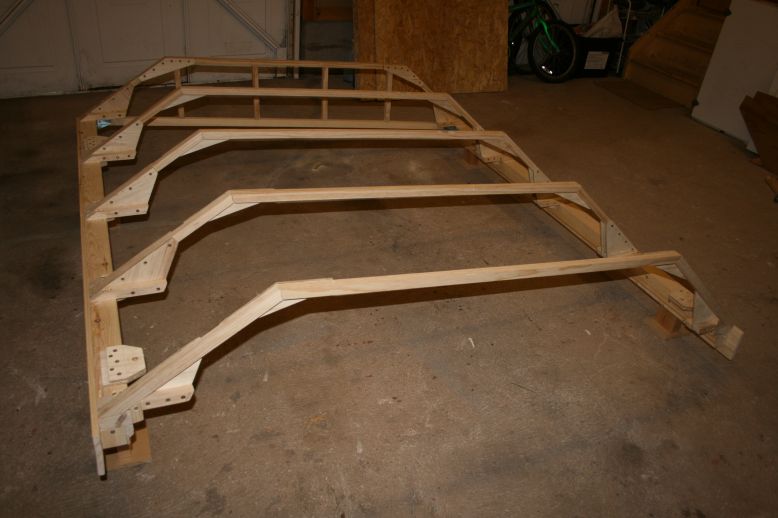
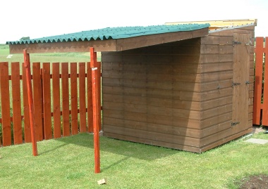
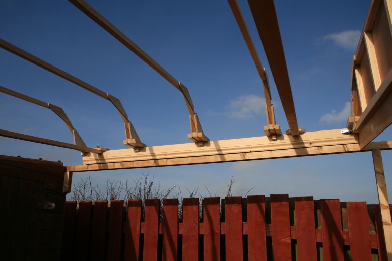
In early 2008 the observatory was refiitted with a new sliding roof in order to permit the installation of a new taller telescope (a 12" LX200 with larger diameter tube and longer fork arms mounted on a new larger equatorial wedge). The new roof is some 35 cm taller than the original flat roof and is open at one end to permit the roof to slide over the telescope. The open end of the roof is closed by means of a hinged gable flap attached to the end wall of the observatory. The sliding roof runs on casters along the low and high walls of the observatory onto two wooden run-off beams that are permanently supported by external posts. Rain-boards on either side of the roof ensure that the roof remain held on the wall and runoff beams. When closed the roof is held fast from within using a combination of flexi-ropes and locks.
|
Clair Observatory with new roof (Feb 2009) |
|
|
Opening the roof is performed by first removing the locking devices and dropping the gable flap followed by sliding the roof with either a push or pulling action using just a single hand. A flexi-rope chain allows the gable flap to be lowered gently to a horizontal position, whilst wooden stops prevent the roof from rolling beyond the end of the runoff beams (The new roof will be slightly quicker to open and shut than the previous roof which require manual installation of two support posts each time the observatory was used, and has the advantage that the roof does not need to be manually lifted on the one side whilst opening/closing). Closing the roof is performed fully in the observatory by pulling on two ropes - one to pull the sliding roof shut and one to lift the gable flap. A small of manual adjustment to the roof position is required to ensure that it mates appropriately with the gable end. (Small wooden guides will be added in due course to facilitate this process automatically).
|
 Testing the new sliding roof (prior to covering frame with board and felt) |
|
|
The frame for the new roof was built using 1"x1" wooden spars with triangular plywood strengtheners, that fixed to two main beams of 1. 5/16" x 2.3/4" wood, one set 8" higher than the other corresponding to the low and high side walls of the observatory. (Normally a run-off roof would have run-off beams that are the same height, but retrofitting a horizontal sliding roof to the existing observatory structure that would also run-over the upstanding telescope demanded that the beams be at different heights) . The roof is topped by 3 sections of 13mm PJB board and covered in bitumen felt. The three sections of roof have slopes of 41 degrees (low side), 6 degrees (top) and 31 degrees (high side). The roof overlap the observatory walls by around 3" and is some 7 feet in length. |
|
|
|
The frame design incorporating the carefully strengthened spars should be sturdy to hold the roof shape despite being open at one end. however the weight the roof might eventually cause a distortion of the roof frame spars with time leading to increased separation between the two side beams with consequential problems with castor wheels tracking and closure of the gable flap. Options to retro-strength the roof spars have been considered for this eventuality. For lifting the roof on or the observatory, special wooden cross-beams are added with bolts to ensure firm rigidity of the roof during this critical operation. Whilst the roof is easy to slide with just a single hand it is overall quite heavy and cumbersome and requires 4 people to lift it onto the observatory. (The previous roof required just 2 people to install) |
|
|
|
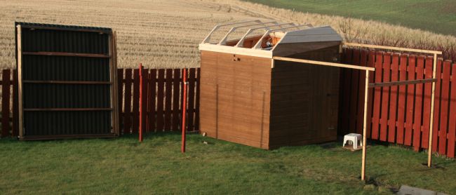
Photo (right) : Test fitting of the new roof. New run-off beams and support posts can be seen on the righthand side of the photo, whilst the previous roof and support posts are visible on left hand side of photo |
 |
|
|
Photo (right) : Test fitting of the new roof frame. Note the two horizontal cross bars are temporary and are used for keeping the integrity of the roof structure during the installation process (or during subsequent relocation). |
|
|
 Drawing of New Roof Design (drawing prepared in Excel) [ larger image] |
||
|---|---|---|
Back to Top
| This Web Page: | Observatory Design, Construction & Modifications |
| Last Updated : | 2015-05-15 |
| Site Owner : | David Richards |
| Home Page : | David's Astronomy Web Site |